Data exchange in Flink is built around the following design principles:
- The control flow for data exchange (i.e., the message passing in order to initiate the exchange) is receiver-initiated, much like the original MapReduce.
- The data flow for data exchange, i.e., the actual transfer of data over the wire is abstracted by the notion of an IntermediateResult, and is pluggable. This means that the system can support both streaming data transfer and batch data transfer with the same implementation.
Data exchange involves several objects, including:
JobManager, the master node, is responsible for scheduling tasks, recovery, and coordination, and holds the big picture of a job via the ExecutionGraph data structure.
TaskManagers, the worker nodes. A TaskManager (TM) executes many tasks concurrently in threads. Each TM also contains one CommunicationManager (CM - shared between tasks), and one MemoryManager (MM - also shared between tasks). TMs can exchange data with each other via standing TCP connections, which are created when needed.
Note that in Flink, it is TaskManagers, not tasks, that exchange data over the network, i.e., data exchange between tasks that live in the same TM is multiplexed over one network connection.
IRS2 IRS2
IRS2
ExecutionGraph: The execution graph is a data structure that contains the “ground truth” about the job computation. It consists of vertices (ExecutionVertex) that represent computation tasks, and intermediate results (IntermediateResultPartition), that represent data produced by tasks. Vertices are linked to the intermediate results they consume via ExecutionEdges (EE):

These are logical data structures that live in the JobManager. They have their runtime equivalent structures that are responsible for the actual data processing that live at the TaskManagers. The runtime equivalent of the IntermediateResultPartition is called ResultPartition.
ResultPartition (RP) represents a chunk of data that a BufferWriter writes to, i.e., a chunk of data produced by a single task. A RP is a collection of Result Subpartitions (RSs). This is to distinguish between data that is destined to different receivers, e.g., in the case of a partitioning shuffle for a reduce or a join.
ResultSubpartition (RS) represents one partition of the data that is created by an operator, together with the logic for forwarding this data to the receiving operator. The specific implementation of a RS determines the actual data transfer logic, and this is the pluggable mechanism that allows the system to support a variety of data transfers. For example, the PipelinedSubpartition is a pipelined implementation to support streaming data exchange. The SpillableSubpartition is a blocking implementation to support batch data exchange.
InputGate: The logical equivalent of the RP at the receiving side. It is responsible for collecting buffers of data and handing them upstream.
InputChannel: The logical equivalent of the RS at the receiving side. It is responsible for collecting buffers of data for a specific partition.
Buffer: See https://cwiki.apache.org/confluence/pages/viewpage.action?pageId=53741525
Serializers and deserializers reliably convert typed records into raw byte buffers and vice versa, handling records that span multiple buffers, etc.
Control flow for data exchange
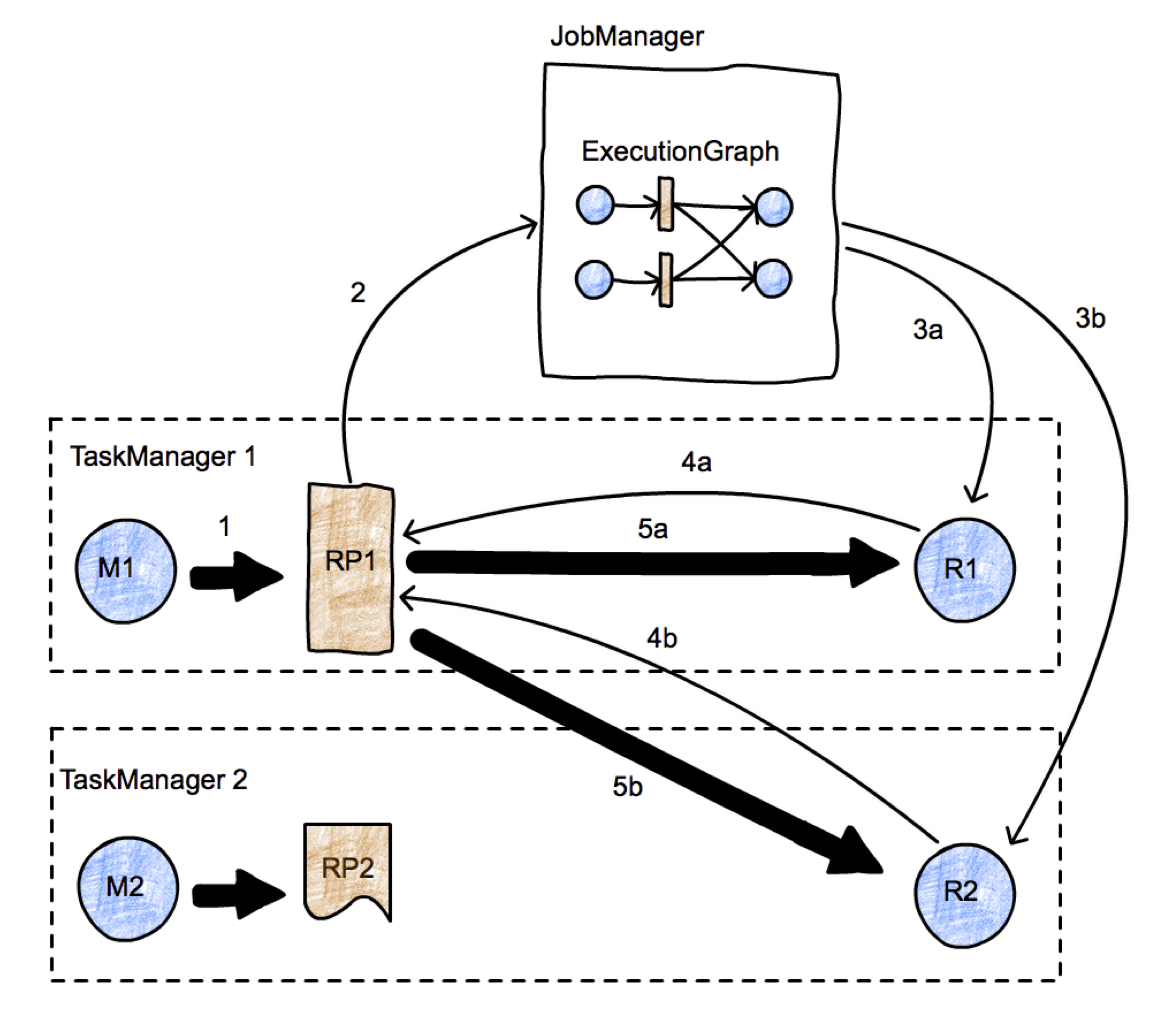
The picture represents a simple map-reduce job with two parallel tasks. We have two TaskManagers, with two tasks each (one map task and one reduce task) running in two different nodes, and one JobManager running in a third node. We focus on the initiation of the transfer between tasks M1 and R2. Data transfers are represented using thick arrows, and messages are represented using thin arrows. First, M1 produces a ResultPartition (RP1) (arrow 1). When the RP becomes available for consumption (we discuss when this is later), it informs the JobManager (arrow 2). The JobManager notifies the intended receivers of this partition (tasks R1 and R2) that the partition is ready. If the receivers have not been scheduled yet, this will actually trigger the deployment of the tasks (arrows 3a, 3b). Then, the receivers will request data from the RP (arrows 4a and 4b). This will initiate the data transfer between the tasks (arrows 5a and 5b), either locally (case 5a), or passing through the network stack of the TaskManagers (5b). This process leaves as a degree of freedom the when a RP decides to inform the JobManager of its availability. For example, if RP1 fully produces itself (and is perhaps written to a file) before informing the JM, the data exchange corresponds roughly to a batch exchange as implemented in Hadoop. If the RP1 informs the JM as soon as its first record is produced, we have a streaming data exchange.
Transfer of a byte buffer between two tasks
![]()
This picture presents in more detail the lifetime of data records as they are shipped from a producer to a consumer. Initially the MapDriver is producing records (collected by a Collector) that are passed to a RecordWriter object. RecordWriters contain a number of serializers (RecordSerializer objects), one per consumer task that will possibly consume these records. For example, in a shuffle or broadcast, there will be as many serializers as the number of consumer tasks. A ChannelSelector selects one or more serializers to place the record to. For example, if records are broadcast, they will be placed in every serializer. If records are hash-partitioned, the ChannelSelector will evaluate the hash value on the record and select the appropriate serializer.
The serializers serialize the records into their binary representation, and place them in fixed-size buffers (records can span multiple buffers). These buffers and handed over to a BufferWriter and written out to an ResultPartition (RP). The RP consists of several subpartitions (ResultSubpartitions - RSs) that collect buffers for specific consumers. In the picture, the buffer is destined for the second reducer (in TaskManager 2), and it is placed in RS2. Since this is the first buffer, RS2 becomes available for consumption (note that this behavior implements a streaming shuffle), and notifies the JobManager of the fact.
The JobManager looks up the consumers of RS2, and notifies TaskManager 2 that a chunck of data is available. The message to TM2 is propagated down to the InputChannel that is supposed to receive this buffer, which in turn notifies RS2 that a network transfer can be initiated. Then, RS2 hands over the buffer to the network stack of TM1, which in turns hands it over to netty for shipping. Network connections are long-running and exist between TaskManagers, not individual tasks.
Once the buffer is received by TM2, it passes through a similar object hierarchy, starting at the InputChannel (the receiver-side equivalent to the IRPQ), going to the InputGate (which contains several ICs), and finally ending up in a RecordDeserializer that produces typed records from buffers and hands them over to the receiving task, in this case a ReduceDriver.
1 Comment
zhangminglei
Very awesome doc.